Peripheral devices
| Depends on | Using Peripherals |
|---|
Where to find them
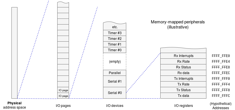
A processor’s address space often contains more than simple memory; some address space is typically reserved for peripheral devices. This space will be protected and thus the access to the devices is via the O.S. A typical interface will have a few memory-mapped registers (8, 16, something like that) so this is tiny compared with the typical overall address space.
In a minority of cases, peripheral devices may be mapped into a separately addressed space but the principle is still similar.
What they are
A peripheral device is an interface between the processor and the outside world. They translate a model of physical phenomena into a representation in digital variables. Two very simple examples:
- A single bit in memory space may connect to an LED, which could be switched ‘off’ or ‘on’ by the state written to that bit.
- A switch may be mapped to a bit so that, when read, it reveals ‘up’ or ‘down’.
- Write data to
Out_portin the memory and see it appear on the LEDs. - Toggle the switches and see the data appear in
In_portin the memory.
Notice that the bits are often (as here) packed together in a single byte or word. (There are uses here for the ‘bitwise operators’ you should have seen in Java (or C).)
Many more complex peripheral devices exist: an example might be a USB interface which can exhibit some complex, semi-autonomous behaviour. Here are a couple of examples: don’t feel obliged to download them.
The details of a given peripheral device are many and varied, and belong more to the ‘hardware’ side of computing. What is important here are the general ways in which software interacts with I/O hardware.
A typical peripheral device will occupy a (small) number of address locations, where the processor can interact with it. Some examples could be:
- SCC2681 – a reasonably simple serial interface device (29pp.).
- This device occupies 16 bytes of the address space.
- The programmer’s details run pp. 11-21, with a register map followed by a bit-by-bit explanation of what each bit does.
- BCM2835 peripherals – a device used for Raspberry Pi computers (205pp.)
- p.5 has somewhat cryptic diagram showing the memory mapping scheme.
- There are ~200 pages of definitions and descriptions of I/O registers in 14 chapters, roughly corresponding to 14 different I/O devices (all on the one chip.)
These are not large datasheets by modern standards.
Do not study these in depth (unless you have a particular purpose) … but it may be worthwhile picking up an appreciation of the sort of interface which is abstracted away in the device drivers.
Analogue interfacing
The examples above illustrate the mapping of digital information (up/down; on/off) into bits. Many real-world phenomena have continuous values… however in a digital computer these are quantised and thus approximated by a nearby value.
If you’ve ever seen values like this is colour #AA3355 then you’ve met this. As long as ‘enough’ bits are used, you can’t see (or hear) the difference from the ‘true’ value. In the case of graphics, you can probably discriminate about 100 intensities (7 bits worth) of red and green – fewer of blue. Thus eight-bits-per-colour is plenty. (There are many animals which are probably better at this!)
Hardware Abstraction Layer (HAL)
Peripheral devices are often hidden under a software hardware abstraction layer, which may be defined to encompass the device drivers or may just cover the peripherals to make the device drivers’ jobs easier.
A main function of an O.S. is to abstract irregular subsystems and regularise them for higher layers; this is one such example.
For those who would like a bit more information…
Illustrative example
A peripheral device provides an interface to/from external hardware as represented by digital data.
Example: a serial input (receiving one bit at a time, e.g. by a radio link) peripheral would typically deserialise the data stream and present the input in a slightly more convenient form. A typical interface might have a register which presents 8-bit, byte data for the processor to read.
There will often be some associated status information.
Example: the serial receiver will have a bit flag – in a processor-readable register – which will be set when a byte is ready to be read and cleared when the data register is read. It is often possible to make this flag cause an interrupt.
There may be set-up (“command”) information.
Example: the serial data rate may be programmable. If you want even more then you’ll need to look at some device datasheets. (We’re not suggesting you do this.)
| Also refer to: | Operating System Concepts, 10th Edition: Chapter 1.2, pages 7-15 |
|---|